Real-Time I/O
Introduction
Sometimes, when BeagleBone Black interacts with the physical world, it needs to respond in a timely manner. For example, your robot has just detected that one of the driving motors needs to turn a bit faster. Systems that can respond quickly to a real event are known as _real-time_ systems. There are two broad categories of real-time systems: soft and hard.
In a _soft real-time_ system, the real-time requirements should be met _most_ of the time, where _most_ depends on the system. A video playback system is a good example. The goal might be to display 60 frames per second, but it doesn’t matter much if you miss a frame now and then. In a 100 percent _hard real-time_ system, you can never fail to respond in time. Think of an airbag deployment system on a car. You can’t even be pass:[<span class=”keep-together”>50 ms late</span>].
Systems running Linux generally can’t do 100 percent hard real-time processing, because Linux gets in the way. However, the Bone has an ARM processor running Linux and two additional 32-bit programmable real-time units (PRUs http://bit.ly/1EzTPZv[Ti AM33XX PRUSSv2]) available to do real-time processing. Although the PRUs can achieve 100 percent hard real-time, they take some effort to use.
This chapter shows several ways to do real-time input/output (I/O), starting with the effortless, yet slower JavaScript and moving up with increasing speed (and effort) to using the PRUs.
Note
In this chapter, as in the others, we assume that you are logged in as +debian+ (as indicated by the +bone$+ prompt). This gives you quick access to the general-purpose input/output (GPIO) ports but you may have to use +sudo+ some times.
I/O with JavaScript
Problem
You want to read an input pin and write it to the output as quickly as possible with JavaScript.
Solution
<sensors_pushbutton> shows how to read a pushbutton switch and <displays_externalLED> controls an external LED. This recipe combines the two to read the switch and turn on the LED in response to it. To make this recipe, you will need:
Breadboard and jumper wires (see app proto)
Pushbutton switch (see app misc)
220 Ω resistor (see app resistor)
LED (see app opto)
Wire up the pushbutton and LED as shown in <realtime_pushLED_fig>.
Diagram for wiring a pushbutton and LED with the LED attached to P9_14
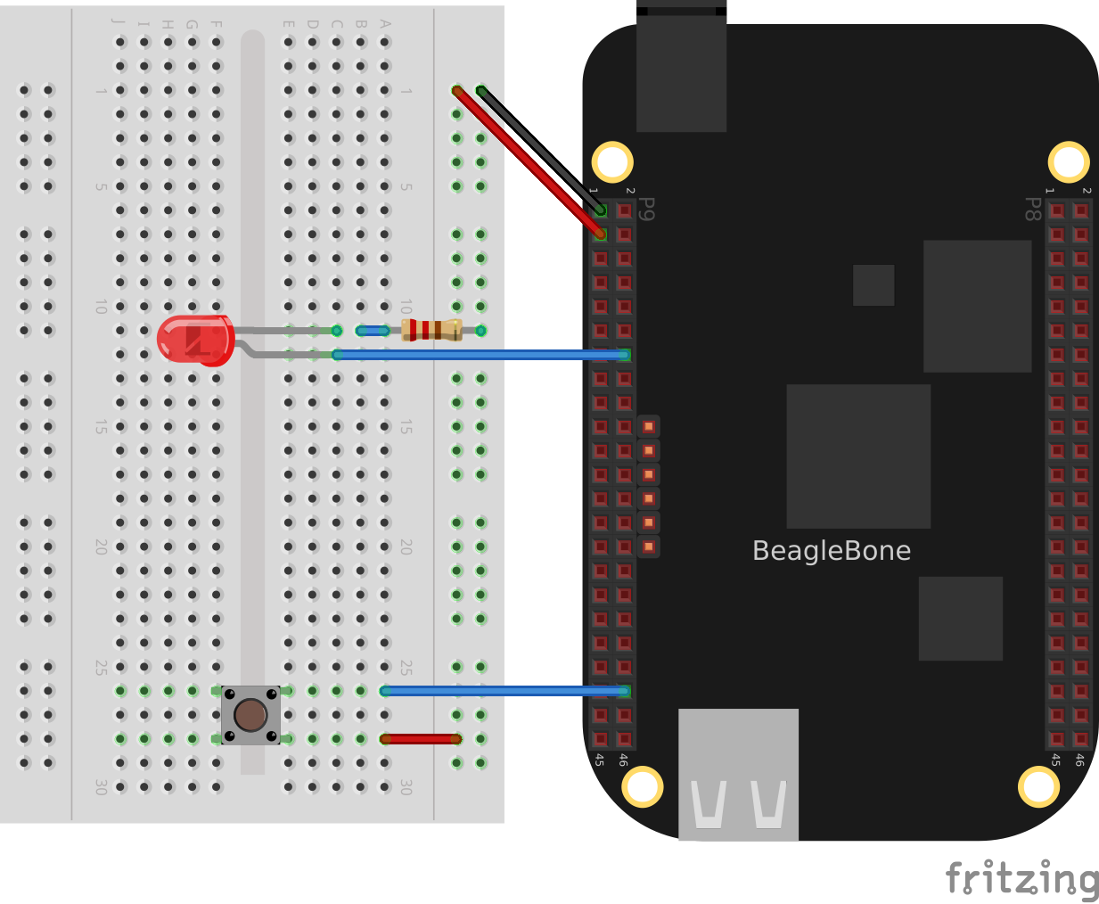
The code in <realtime_pushLED_code> reads GPIO port +P9_42+, which is attached to the pass:[<span class=”keep-together”>pushbutton</span>], and turns on the LED attached to +P9_12+ when the button is pushed.
Monitoring a pushbutton (pushLED.py)
include::code/pushLED.py
Monitoring a pushbutton (pushLED.js)
include::code/pushLED.js
Add the code to a file named _pushLED.js_ and run it by using the following commands:
bone$ <strong>chmod +x pushLED.js</strong>
bone$ <strong>./pushLED.js</strong>
data = 0
data = 0
data = 1
data = 1
^C
Press ^C (Ctrl-C) to stop the code.
Discussion
I/O with C
Problem
You want to use the C language to process inputs in real time, or Python/JavaScript isn’t fast enough.
Solution
<realtime_JavaScript> shows how to control an LED with a pushbutton using JavaScript. This recipe accomplishes the same thing using C. It does it in the same way, opening the correct /sys/class/gpio files and reading an writing them.
Wire up the pushbutton and LED as shown in <realtime_pushLED_fig>. Then add the code in <realtime_pushLED_c_code> to a file named _pushLED.c_.
Code for reading a switch and blinking an LED (pushLED.c)
include::code/pushLED.c[]
Compile and run the code:
bone$ <strong>gcc -o pushLED pushLED.c</strong>
bone$ <strong>./pushLED</strong>
state: 1
state: 1
state: 0
state: 0
state: 0
state: 1
^C
The code responds quickly to the pushbutton. If you need more speed, comment-out the +printf()+ and the +sleep()+.
Discussion
I/O with devmem2
Problem
Your C code isn’t responding fast enough to the input signal. You want to read the GPIO registers directly.
Solution
The solution is to use a simple utility called +devmem2+, with which you can read and write registers from the command line.
Warning
This solution is much more involved than the previous ones. You need to understand binary and hex numbers and be able to read the http://bit.ly/1B4Cm45[AM335x Technical Reference Manual].
First, download and install +devmem2+:
bone$ <strong>wget http://free-electrons.com/pub/mirror/devmem2.c</strong>
bone$ <strong>gcc -o devmem2 devmem2.c</strong>
bone$ <strong>sudo mv devmem2 /usr/bin</strong>
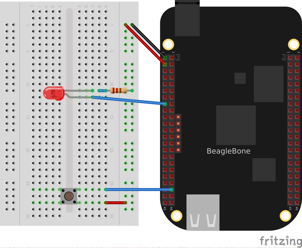
This solution will read a pushbutton attached to +P9_42+ and flash an LED attached to +P9_13+. Note that this is a change from the previous solutions that makes the code used here much simpler. Wire up your Bone as shown in <realtime_pushLEDmmap_fig>.
Diagram for wiring a pushbutton and LED with the LED attached to P9_13
Now, flash the LED attached to +P9_13+ using the Linux +sysfs+ interface (<kernel_gpio_sysfs>). To do this, first look up which GPIO number +P9_13+ is attached to by referring to <tips_cape_headers_digital>. Finding +P9_13+ at GPIO 31, export GPIO 31 and make it an output:
bone$ <strong>cd cd /sys/class/gpio/</strong>
bone$ <strong>echo 31 > export</strong>
bone$ <strong>cd gpio31</strong>
bone$ <strong>echo out > direction</strong>
bone$ <strong>echo 1 > value</strong>
bone$ <strong>echo 0 > value</strong>
The LED will turn on when +1+ is echoed into +value+ and off when +0+ is echoed.
Now that you know the LED is working, look up its memory address. This is where things get very detailed. First, download the http://bit.ly/1B4Cm45[AM335x Technical Reference Manual]. Look up +GPIO0+ in the Memory Map chapter (sensors). Table 2-2 indicates that +GPIO0+ starts at address +0x44E0_7000+. Then go to Section 25.4.1, “GPIO Registers.” This shows that +GPIO_DATAIN+ has an offset of +0x138+, +GPIO_CLEARDATAOUT+ has an offset of +0x190+, and +GPIO_SETDATAOUT+ has an offset of +0x194+.
This means you read from address +0x44E0_7000+ + +0x138+ = +0x44E0_7138+ to see the status of the LED:
bone$ <strong>sudo devmem2 0x44E07138</strong>
/dev/mem opened.
Memory mapped at address 0xb6f8e000.
Value at address 0x44E07138 (0xb6f8e138): 0xC000C404
The returned value +0xC000C404+ (+1100 0000 0000 0000 1100 0100 0000 0100+ in binary) has bit 31 set to +1+, which means the LED is on. Turn the LED off by writing +0x80000000+ (+1000 0000 0000 0000 0000 0000 0000 0000+ binary) to the +GPIO_CLEARDATA+ register at +0x44E0_7000+ + +0x190+ = +0x44E0_7190+:
bone$ <strong>sudo devmem2 0x44E07190 w 0x80000000</strong>
/dev/mem opened.
Memory mapped at address 0xb6fd7000.
Value at address 0x44E07190 (0xb6fd7190): 0x80000000
Written 0x80000000; readback 0x0
The LED is now off.
You read the pushbutton switch in a similar way. <tips_cape_headers_digital> says +P9_42+ is GPIO 7, which means bit 7 is the state of +P9_42+. The +devmem2+ in this example reads +0x0+, which means all bits are +0+, including GPIO 7. Section 25.4.1 of the Technical Reference Manual instructs you to use offset +0x13C+ to read +GPIO_DATAOUT+. Push the pushbutton and run +devmem2+:
bone$ <strong>sudo devmem2 0x44e07138</strong>
/dev/mem opened.
Memory mapped at address 0xb6fe2000.
Value at address 0x44E07138 (0xb6fe2138): 0x4000C484
Here, bit 7 is set in +0x4000C484+, showing the button is pushed.
Discussion
This is much more tedious than the previous methods, but it’s what’s necessary if you need to minimize the time to read an input. <realtime_mmap> shows how to read and write these addresses from C.
I/O with C and mmap()
Problem
Your C code isn’t responding fast enough to the input signal.
Solution
In smaller processors that aren’t running an operating system, you can read and write a given memory address directly from C. With Linux running on Bone, many of the memory locations are hardware protected, so you can’t accidentally access them directly.
This recipe shows how to use +mmap()+ (memory map) to map the GPIO registers to an array in C. Then all you need t o do is access the array to read and write the registers.
Warning
This solution is much more involved than the previous ones. You need to understand binary and hex numbers and be able to read the AM335x Technical Reference Manual.
This solution will read a pushbutton attached to +P9_42+ and flash an LED attached to +P9_13+. Note that this is a change from the previous solutions that makes the code used here much simpler.
Tip
See <realtime_devmem2> for details on mapping the GPIO numbers to memory addresses.
Add the code in <realtime_pushLEDmmap_h> to a file named _pushLEDmmap.h_.
Memory address definitions (pushLEDmmap.h)
include::code/pushLEDmmap.h[pushLEDmmap.h]
Add the code in <realtime_pushLEDmmap_c> to a file named _pushLEDmmap.c_. .. _realtime_pushLEDmmap_c:
Code for directly reading memory addresses (pushLEDmmap.c)
include::code/pushLEDmmap.c[pushLEDmmap.c]
Now, compile and run the code:
bone$ <strong>gcc -O3 pushLEDmmap.c -o pushLEDmmap</strong>
bone$ <strong>sudo ./pushLEDmmap</strong>
Mapping 44E07000 - 44E08000 (size: 1000)
GPIO mapped to 0xb6fac000
GPIO SETDATAOUTADDR mapped to 0xb6fac194
GPIO CLEARDATAOUT mapped to 0xb6fac190
Start copying GPIO_07 to GPIO_31
^C
Ctrl-C pressed, cleaning up and exiting...
The code is in a tight +while+ loop that checks the status of GPIO 7 and copies it to GPIO 31.
Discussion
Tighter Delay Bounds with the PREEMPT_RT Kernel
Problem
You want to run real-time processes on the Beagle, but the OS is slowing things down.
Solution
The Kernel can be compiled with PREEMPT_RT enabled which reduces the delay from when a thread is scheduled to when it runs.
Switching to a PREEMPT_RT kernel is rather easy, but be sure to follow the steps in the Discussion to see how much the latencies are reduced.
First see which kernel you are running:
bone$ <strong>uname -a</strong>
Linux breadboard-home 5.10.120-ti-r47 #1bullseye SMP PREEMPT Tue Jul 12 18:59:38 UTC 2022 armv7l GNU/Linux
I'm running a 5.10 kernel.  Remember the whole string, +5.10.120-ti-r47+, for later.
Go to https://forum.beagleboard.org/t/debian-10-x-11-x-kernel-updates/30928[kernel update] and look for +5.10+.
The regular and RT kernels
In <realtime_kernel_update_fig> you see the reular kernel on top and the RT below.
We want the RT one.
bone$ <strong>sudo apt update</strong>
bone$ <strong>sudo apt install bbb.io-kernel-5.10-ti-rt-am335x</strong>
Note
Use the am57xx if you are using the BeagleBoard AI or AI64.
Before rebooting, edit +/boot/uEnv.txt+ to start with:
#Docs: http://elinux.org/Beagleboard:U-boot_partitioning_layout_2.0

# uname_r=5.10.120-ti-r47
uname_r=5.10.120-ti-rt-r47
#uuid=
#dtb=
+uname_r+ tells the boot loader which kernel to boot. Here we’ve commented out the regular kernel and left in the RT kernel. Next time you boot you’ll be running the RT kernel. Don’t reboot just yet. Let’s gather some latency data first.
Discussion
Bootlin’s preempt_rt workshop looks like a good workshop on PREEMPT RT. Their slides say:
One way to implement a multi-task Real-Time Operating System is to have a preemptible system
Any task can be interrupted at any point so that higher priority tasks can run
Userspace preemption already exists in Linux
The Linux Kernel also supports real-time scheduling policies
However, code that runs in kernel mode isn’t fully preemptible
The Preempt-RT patch aims at making all code running in kernel mode preemptible
The workshop goes into many details on how to get real-time performance on Linux. Checkout their slides and labs. Though you can skip the first lab since we present a simpler way to get the RT kernel running.
Cyclictest
+cyclictest+ is one tool for measuring the latency from when a thread is schduled and when it runs. The +code/rt+ directory in the git repo has some scripts for gathering latency data and plotting it. Here’s how to run the scripts.
First look in <realtime_install_fig> to see what to install.
include::code/rt/install.sh
Open up another window and start something that will create a load on the Bone, then run the following:
bone$ <strong>time sudo ./hist.gen > nort.hist</strong>
<realtime_hist_gen_fig> shows what’s being run. It defaults to 100,000 loops, so it takes a while. The data is saved in +nort.hist+, which stands for no RT histogram.
hist.gen
include::code/rt/hist.gen
Note
If you get an error:
Unable to change scheduling policy! Probably missing capabilities, either run as root or increase RLIMIT_RTPRIO limits
try running ./setup.sh. If that doesn’t work try:
bone$ sudo bash
bone# ulimit -r unlimited
bone# ./hist.gen > nort.hist
bone# exit
Now you are ready to reboot into the RT kernel and run the test again.
bone$ <strong>reboot</strong>
After rebooting:
bone$ <strong>uname -a</strong>
Linux breadboard-home 5.10.120-ti-rt-r47 #1bullseye SMP PREEMPT RT Tue Jul 12 18:59:38 UTC 2022 armv7l GNU/Linux
Congratulations you are running the RT kernel.
Note
If the Beagle appears to be running (the LEDs are flashing) but you are having trouble connecting via +ssh 192.168.7.2+, you can try connecting using the approach shown in <tips_FTDI>.
Now run the scipt again (note it’s being saved in +rt.hist+ this time.)
bone$ <strong>time sudo ./hist.gen > rt.hist</strong>
Note
At this point yoou can edit +/boot/uEnt.txt+ to boot the non RT kernel and reboot.
Now it’s time to plot the results.
bone$ <strong>gnuplot hist.plt</strong>
This will generate the file cyclictest.png which contains your plot. It should look like:
Histogram of Non-RT and RT kernels running cyclictest
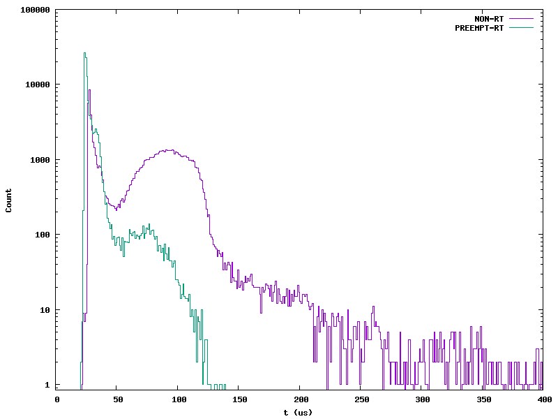
Notice the NON-RT data have much longer latenices. They may not happen often (fewer than 10 times in each bin), but they are occuring and may be enough to miss a real-time deadline.
The PREEMPT-RT times are all under a 150 pass:[μ]s.
I/O with simpPRU
Problem
You require better timing than running C on the ARM can give you.
Solution
The AM335x processor on the Bone has an ARM processor that is running Linux, but it also has two 32-bit PRUs that are available for processing I/O. It takes a fair amount of understanding to program the PRU. Fortunately, simpPRU is an intuitive language for PRU which compiles down to PRU C. This solution shows how to use it.
Background
simpPRU