Sensors
Introduction
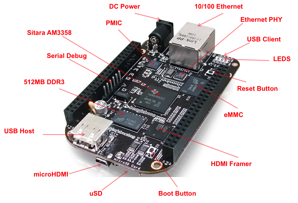
In this chapter, you will learn how to sense the physical world with BeagleBone Black. Various types of electronic sensors, such as cameras and microphones, can be connected to the Bone using one or more interfaces provided by the standard USB 2.0 host port, as shown in sensor host port.
Note
All the examples in the book assume you have cloned the Cookbook repository on www.github.com. Go here basic repo for instructions.
The USB 2.0 host port
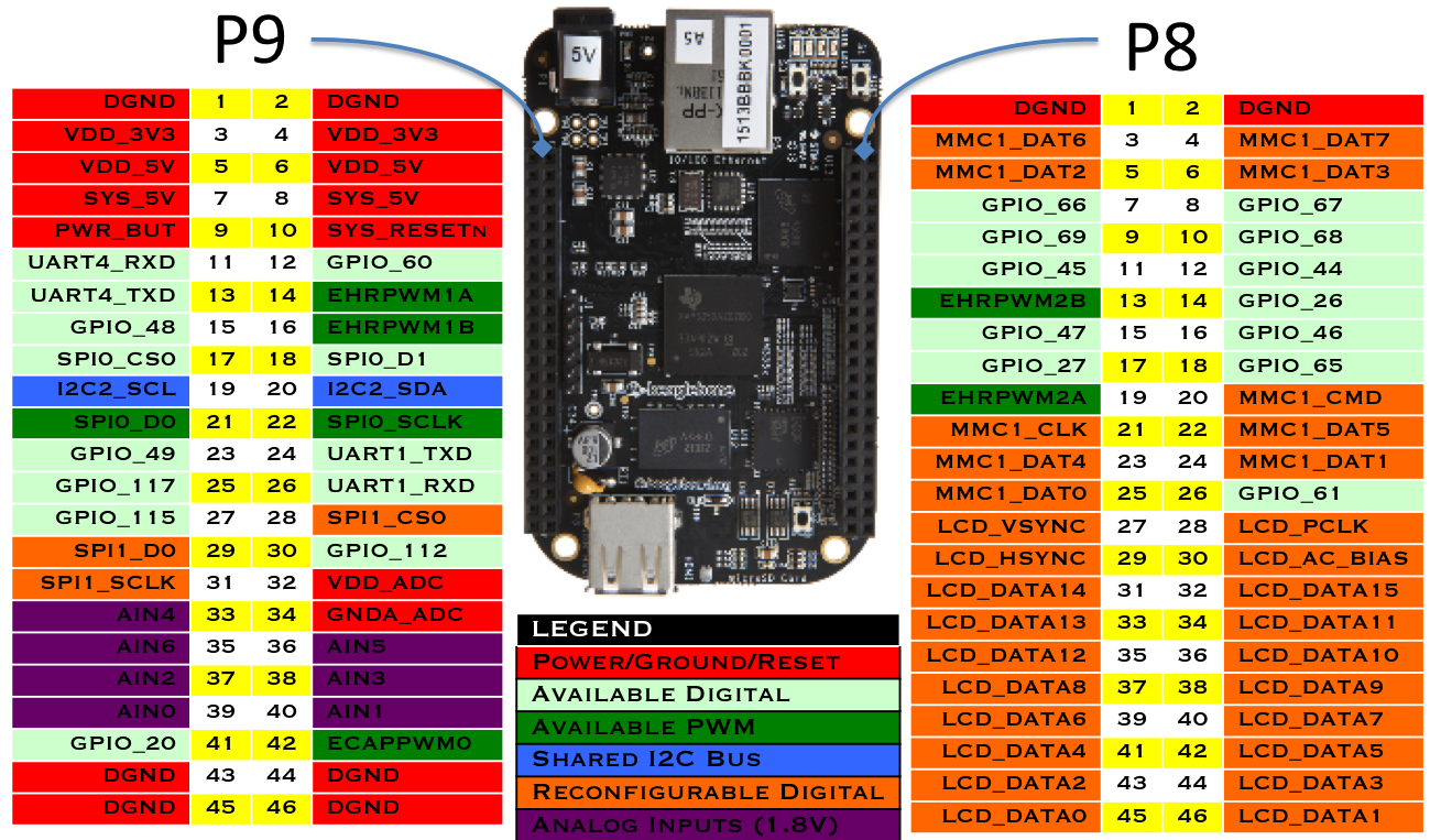
The two 46-pin cape headers (called +P8+ and +P9+) along the long edges of the board (sensors P8 & P9) provide connections for cape add-on boards, digital and analog sensors, and more.
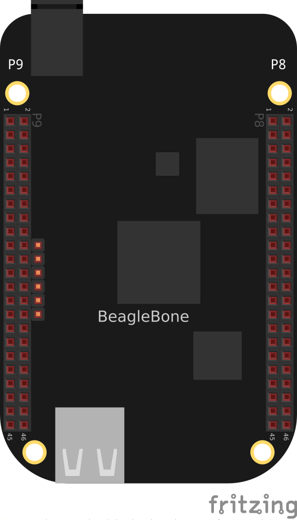
Cape Headers P8 and P9
The simplest kind of sensor provides a single digital status, such as off or on, and can be handled by an input mode of one of the Bone’s 65 general-purpose input/output (GPIO) pins. More complex sensors can be connected by using one of the Bone’s seven analog-to-digital converter (ADC) inputs or several I^2^C buses.
display discusses some of the output mode usages of the GPIO pins.
All these examples assume that you know how to edit a file (basic vsc) and run it, either within the Visual Studio Code (VSC) integrated development environment (IDE) or from the command line (shell tips).
Choosing a Method to Connect Your Sensor
Problem
You want to acquire and attach a sensor and need to understand your basic options.
Solution
sensor cape headers shows many of the possibilities for connecting a sensor.
Sensor Connection Modes
Choosing the simplest solution available enables you to move on quickly to addressing other system aspects. By exploring each connection type, you can make more informed decisions as you seek to optimize and troubleshoot your design.
Discussion
Input and Run a Python or JavaScript Application for Talking to Sensors
Problem
You have your sensors all wired up and your Bone booted up, and you need to know how to enter and run your code.
Solution
You are just a few simple steps from running any of the recipes in this book.
Plug your Bone into a host computer via the USB cable (basic out of the box).
Start Visual Studio Code (basic vsc).
In the +bash+ tab (as shown in sensors vsc bash), run the following commands:
bone$ cd

bone$ cd BoneCookbook/docs/02sensors/code
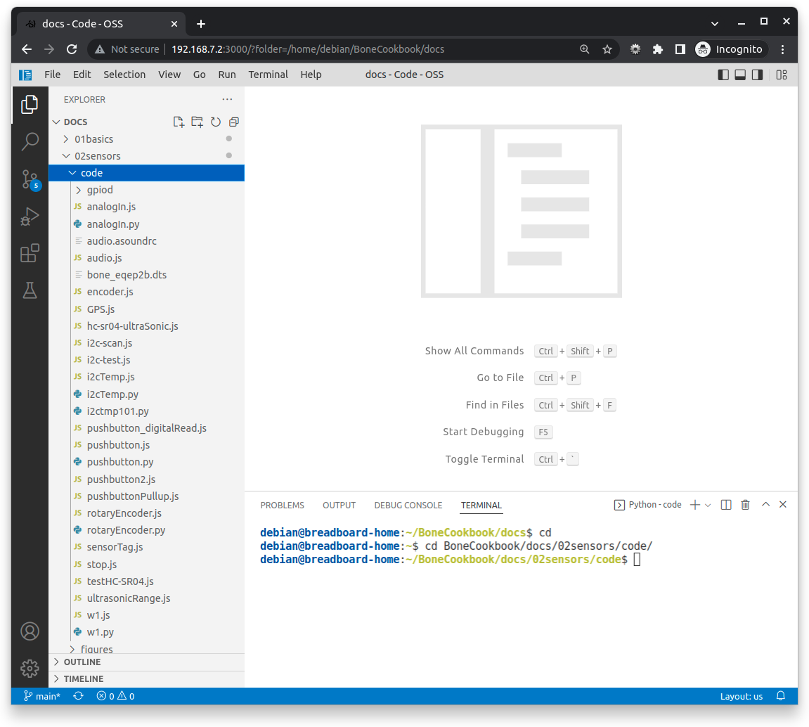
VSC bash tab
Here, we issued the change directory (+cd+) command without specifying a target directory. By default, it takes you to your home directory. Notice that the prompt has changed to reflect the change.
Note
If you log in as +debian+, your home is /home/debian. If you were to create a new user called newuser, that user’s home would be /home/newuser. By default, all non-root (non-superuser) users have their home directories in /home.
Note
All the examples in the book assume you have cloned the Cookbook repository on www.github.com. Go here basic repo for instructions.
Double-click the pushbutton.py file to open it.
Press ^S (Ctrl-S) to save the file. (You can also go to the File menu in VSC and select Save to save the file, but Ctrl-S is easier.) Even easier, VSC can be configured to autosave every so many seconds.
In the +bash+ tab, enter the following commands:
root@beaglebone:~/boneSensors# ./pushbutton.js
data= 0
data= 0
data= 1
data= 1
^C
This process will work for any script in this book.
Discussion
Reading the Status of a Pushbutton or Magnetic Switch (Passive On/Off Sensor)
Problem
You want to read a pushbutton, a magnetic switch, or other sensor that is electrically open or closed.
Solution
Connect the switch to a GPIO pin and read from the proper place in /sys/class/gpio.
To make this recipe, you will need:
Breadboard and jumper wires (see app proto)
Pushbutton switch (see app misc)
Magnetic reed switch (optional, see <app misc app_misc>)
You can wire up either a pushbutton, a magnetic reed switch, or both on the Bone, as shown in figure below.

Bone with pushbutton
The code in js pushbutton code reads GPIO port P9_42, which is attached to the pushbutton.
include::code/pushbutton.py
include::code/pushbutton.js
Put this code in a file called pushbutton.js following the steps in sensor getting started. In the VSC bash tab, run it by using the following commands:
bone$ ./pushbutton.js
data = 0
data = 0
data = 1
data = 1
^C
The command runs it. Try pushing the button. The code reads the pin and prints its current value.
You will have to press ^C (Ctrl-C) to stop the code.
If you want to use the magnetic reed switch wired as shown in javascript pushbutton, change +P9_42+ to +P9_26+ which is gpio +14+.
Discussion
Mapping Header Numbers to gpio Numbers
Problem
You have a sensor attached to the P8 or P9 header and need to know which gpio pin it’s using.
Solution
The +gpioinfo+ command displays information about all the P8 and P9 header pins. To see the info for just one pin, use +grep+.
bone$ gpioinfo | grep -e chip -e P9.42
gpiochip0 - 32 lines:
        line   7: "P8_42A [ecappwm0]" "P9_42" input active-high [used]
gpiochip1 - 32 lines:
gpiochip2 - 32 lines:
gpiochip3 - 32 lines:
This shows P9_42 is on chip 0 and pin 7. To find the gpio number multiply the chip number by 32 and add it to the pin number. This gives 0*32+7=7.
For P9_26 you get:
bone$ gpioinfo | grep -e chip -e P9.26
gpiochip0 - 32 lines:
        line  14: "P9_26 [uart1_rxd]" "P9_26" input active-high [used]
gpiochip1 - 32 lines:
gpiochip2 - 32 lines:
gpiochip3 - 32 lines:
0*32+14=14, so the P9_26 pin is gpio 14.
Reading a Position, Light, or Force Sensor (Variable Resistance Sensor)
Problem
You have a variable resistor, force-sensitive resistor, flex sensor, or any of a number of other sensors that output their value as a variable resistance, and you want to read their value with the Bone.
Solution
Use the Bone’s analog-to-digital converters (ADCs) and a resistor divider circuit to detect the resistance in the sensor.
The Bone has seven built-in analog inputs that can easily read a resistive value. cape header analog sensors shows them on the lower part of the +P9+ header.
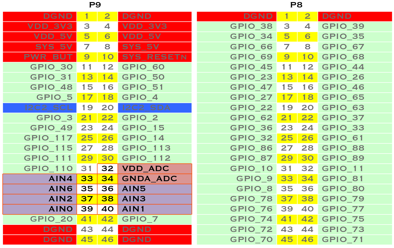
Seven analog inputs on P9 header
To make this recipe, you will need:
Breadboard and jumper wires (see app proto)
10 kΩ trimpot (see app resistor) or
Flex resistor (optional, see app resistor)
22 kΩ resistor (see app resistor)
A variable resistor with three terminals
sensor analogIn shows a simple variable resistor (trimpot) wired to the Bone. One end terminal is wired to the ADC 1.8 V power supply on pin P9_32, and the other end terminal is attached to the ADC ground (P9_34). The middle terminal is wired to one of the seven analog-in ports (P9_36).
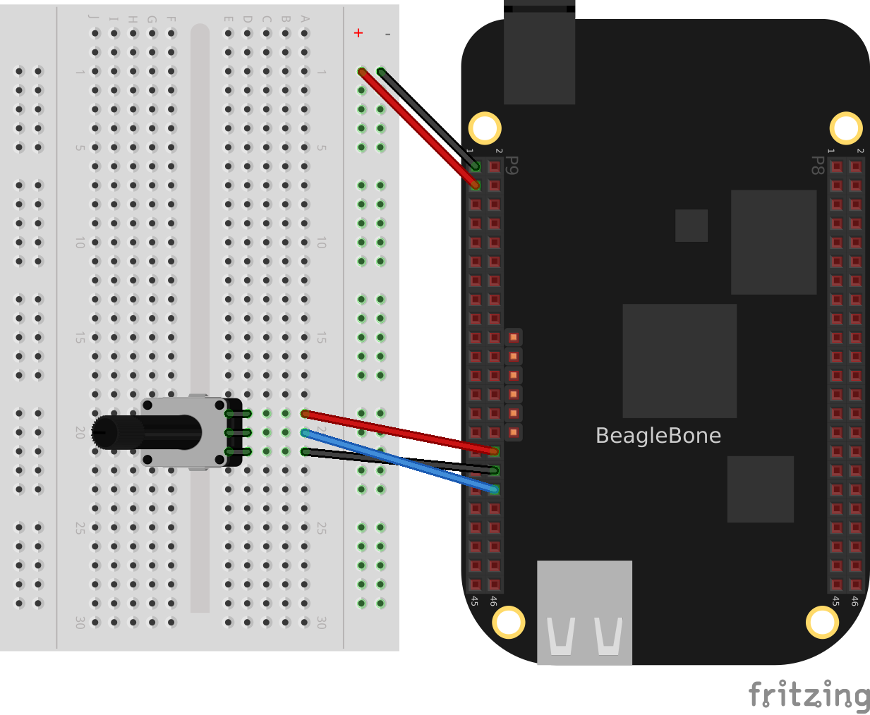
Wiring a 10k variable resistor (trimpot) to an ADC port
sensor analogIn code shows the BoneScript code used to read the variable resistor. Add the code to a file called _analogIn.js_ and run it; then change the resistor and run it again. The voltage read will change.
Reading an analog voltage (analogIn.py)
include::code/analogIn.py
Reading an analog voltage (analogIn.js)
include::code/analogIn.js[]
Note
The code in sensor analogIn code outputs a value between 0 and 4096.
A variable resistor with two terminals
Some resistive sensors have only two terminals, such as the flex sensor in sensor flex resistor The resistance between its two terminals changes when it is flexed. In this case, we need to add a fixed resistor in series with the flex sensor. sensor flex resistor shows how to wire in a 22 kΩ resistor to give a voltage to measure across the flex sensor.
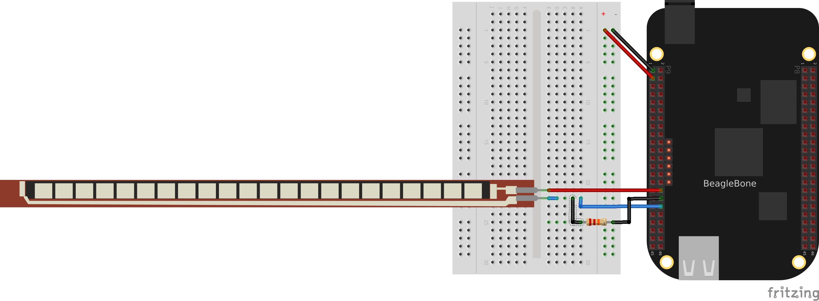
Flex Resistor
The code in py analogIn code and sensors analogIn code also works for this setup.
Discussion
Reading a Distance Sensor (Analog or Variable Voltage Sensor)
Problem
You want to measure distance with a LV-MaxSonar-EZ1 Sonar Range Finder, which outputs a voltage in proportion to the distance.
Solution
To make this recipe, you will need:
All you have to do is wire the EZ1 to one of the Bone’s analog-in pins, as shown in this figure<sensors_ultrasonic_fig>. The device outputs ~6.4 mV/in when powered from 3.3 V.
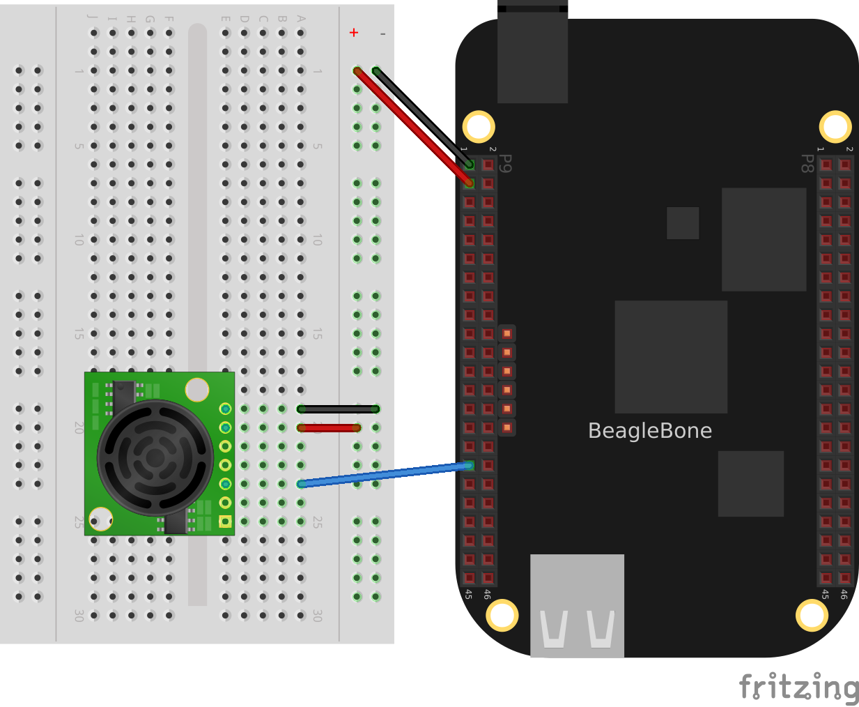
Wiring the LV-MaxSonar-EZ1 Sonar Range Finder to the P9_33 analog-in port
Ultrasonic sensor range code shows the code that reads the sensor at a fixed interval.
Reading an analog voltage (ultrasonicRange.py)
include::code/ultrasonicRange.py[]
Reading an analog voltage (ultrasonicRange.js)
include::code/ultrasonicRange.js[]
Discussion
Reading a Distance Sensor (Variable Pulse Width Sensor)
// TODO
Problem
You want to use a HC-SR04 Ultrasonic Range Sensor with BeagleBone Black.
Solution
The HC-SR04 Ultrasonic Range Sensor (shown in hc sr04 sensor image <sensors_hc_sr04_image_fig>) works by sending a trigger pulse to the Trigger input and then measuring the pulse width on the Echo output. The width of the pulse tells you the distance.
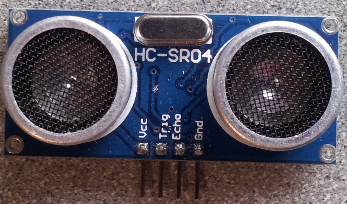
HC-SR04 Ultrasonic range sensor
To make this recipe, you will need:
Breadboard and jumper wires (see app proto)
10 kΩ and 20 kΩ resistors (see app resistor)
HC-SR04 Ultrsonic Range Sensor (see app misc)
Wire the sensor as shown in hc sr04 sensor. Note that the HC-SR04 is a 5 V device, so the banded wire (running from P9_7 on the Bone to VCC on the range finder) attaches the HC-SR04 to the Bone’s 5 V power supply.
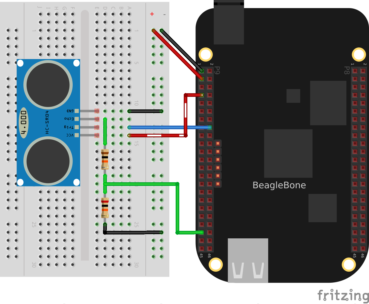
Wiring an HC-SR04 Ultrasonic Sensor
hc sr04 shows BoneScript code used to drive the HC-SR04.
Driving a HC-SR04 ultrasound sensor (hc-sr04-ultraSonic.js)
include::code/hc-sr04-ultraSonic.js[]
This code is more complex than others in this chapter, because we have to tell the device when to start measuring and time the return pulse.
Discussion
Accurately Reading the Position of a Motor or Dial
Problem
You have a motor or dial and want to detect rotation using a rotary encoder.
Solution
Use a rotary encoder (also called a quadrature encoder) connected to one of the Bone’s eQEP ports, as shown in digital rotary encoder figure.
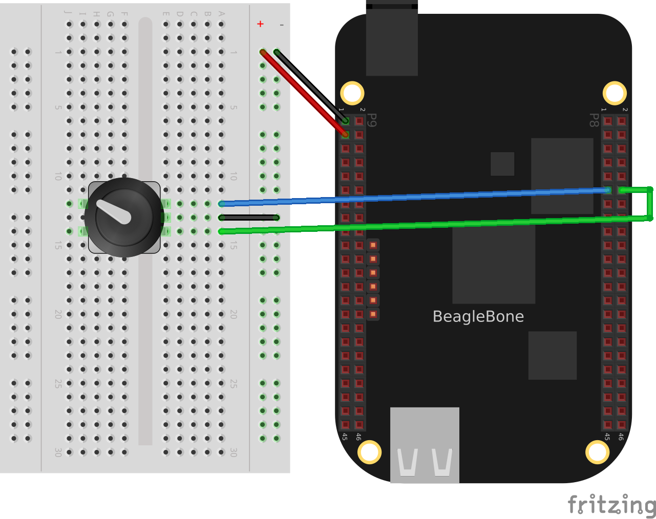
Wiring a rotary encoder using eQEP2
On the BeagleBone and PocketBeage the three encoders are:
eQEP0 |
P9.27 and P9.42 OR P1_33 and P2_34 |
eQEP |
P9.33 and P9.35 |
eQEP2 |
P8.11 and P8.12 OR P2_24 and P2_33 |
On the AI it’s:
eQEP1 |
P8.33 and P8.35 |
eQEP2 |
P8.11 and P8.12 or P9.19 and P9.41 |
eQEP3 |
P8.24 and P8.25 or P9.27 and P9.42 |
To make this recipe, you will need:
We are using a quadrature rotary encoder, which has two switches inside that open and close in such a manner that you can tell which way the shaft is turning. In this particular encoder, the two switches have a common lead, which is wired to ground. It also has a pushbutton switch wired to the other side of the device, which we aren’t using.
Wire the encoder to +P8_11+ and +P8_12+, as shown in digital rotary encoder.
BeagleBone Black has built-in hardware for reading up to three encoders. Here, we’ll use the eQEP2 encoder via the Linux +count+ subsystem.
Then run the following commands:
bone$ config-pin P8_11 qep
bone$ config-pin P8_12 qep
bone$ show-pins | grep qep
P8.12        12 fast rx  up  4 qep 2 in A    ocp/P8_12_pinmux (pinmux_P8_12_qep_pin)
P8.11        13 fast rx  up  4 qep 2 in B    ocp/P8_11_pinmux (pinmux_P8_11_qep_pin)
This will enable eQEP2 on pins +P8_11+ and P8_12. The 2 after the +qep+ returned by show-pins shows it’s eQEP2.
Finally, add the code in digital rotary encoder to a file named rotaryEncoder.js and run it.
Reading a rotary encoder (rotaryEncoder.py)
include::code/rotaryEncoder.py
Reading a rotary encoder (rotaryEncoder.js)
Try rotating the encoder clockwise and counter-clockwise. You’ll see an output like this:
The values you get for +data+ will depend on which way you are turning the device and how quickly. You will need to press ^C (Ctrl-C) to end.
Discussion
See Also
You can also measure rotation by using a variable resistor (see sensors analogIn).
Acquiring Data by Using a Smart Sensor over a Serial Connection
// TODO
Problem
You want to connect a smart sensor that uses a built-in microcontroller to stream data, such as a global positioning system (GPS), to the Bone and read the data from it.
Solution
The Bone has several serial ports (UARTs) that you can use to read data from an external microcontroller included in smart sensors, such as a GPS. Just wire one up, and you’ll soon be gathering useful data, such as your own location.
Here’s what you’ll need:
Wire your GPS, as shown in digital GPS.
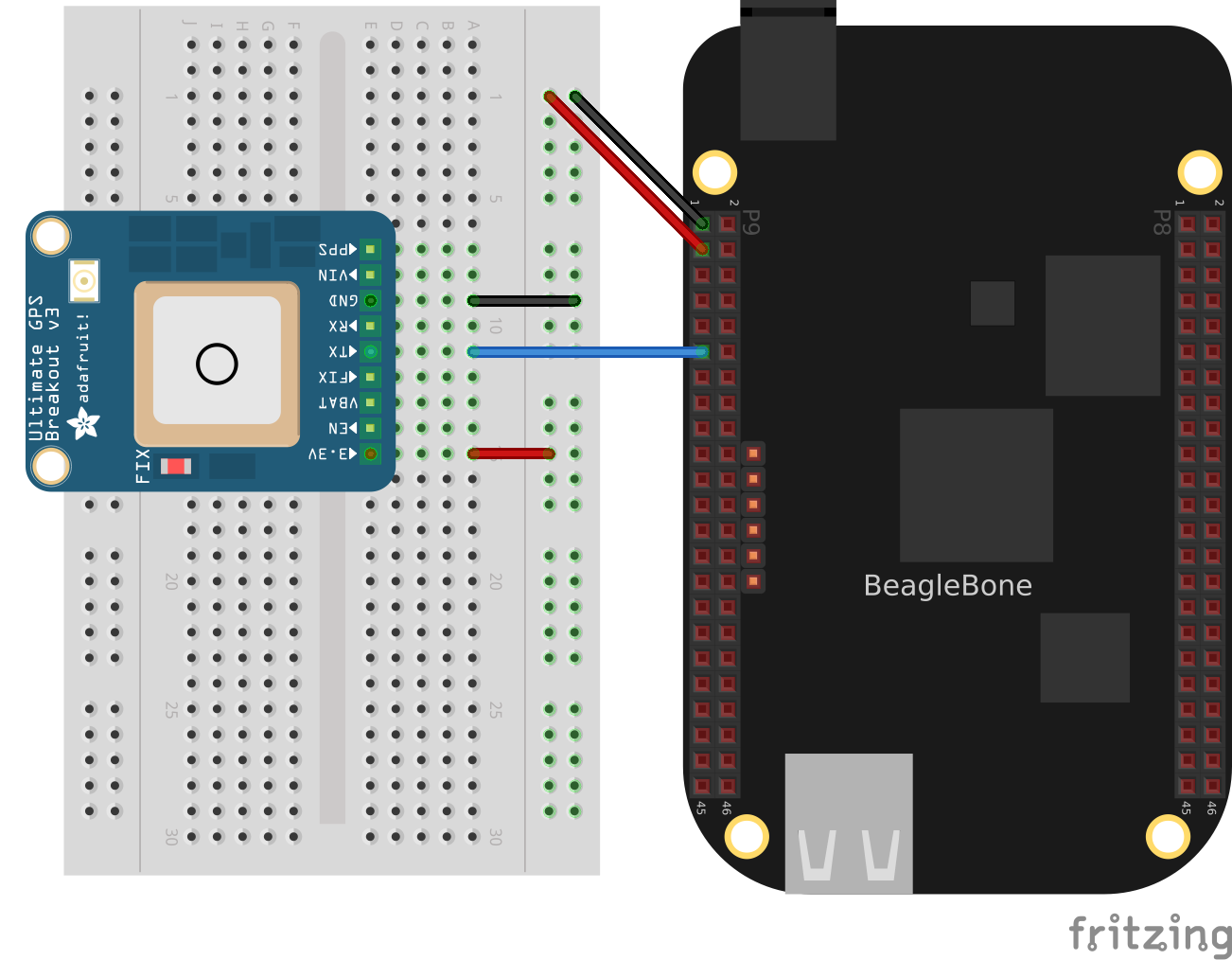
Wiring a GPS to UART 4
The GPS will produce raw National Marine Electronics Association (NMEA) data that’s easy for a computer to read, but not for a human. There are many utilities to help convert such sensor data into a human-readable form. For this GPS, run the following command to load a NMEA parser:
bone$ npm install -g nmea
Running the code in digital GPD code will print the current location every time the GPS outputs it.
Talking to a GPS with UART 4 (GPS.js)
include::code/GPS.js[]
If you don’t need the NMEA formatting, you can skip the npm part and remove the lines in the code that refer to it.
Note
If you get an error like this
add this line to the end of file /usr/local/lib/node_modules/bonescript/serial.js:
exports.serialParsers = m.module.parsers;
Discussion
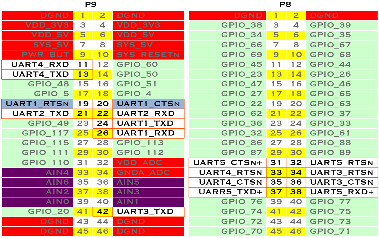
Table of UART outputs
Measuring a Temperature
Problem
You want to measure a temperature using a digital temperature sensor.
Solution
The TMP101 sensor is a common digital temperature sensor that uses a standard I^2^C-based serial protocol.
To make this recipe, you will need:
Breadboard and jumper wires (see app proto)
Two 4.7 kΩ resistors (see app resistor)
TMP101 temperature sensor (see app ic)
Wire the TMP101, as shown in i2c temprature sensor.
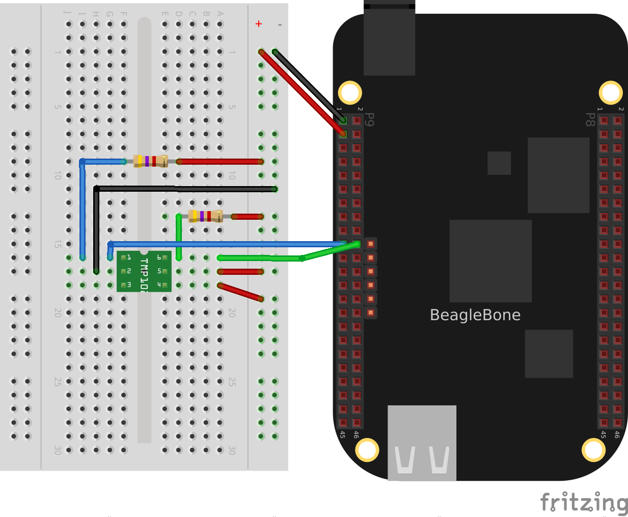
Wiring an I^2^C TMP101 temperature sensor
There are two I^2^C buses brought out to the headers. sensor cap headers i2c shows that you have wired your device to I^2^C bus +2+.
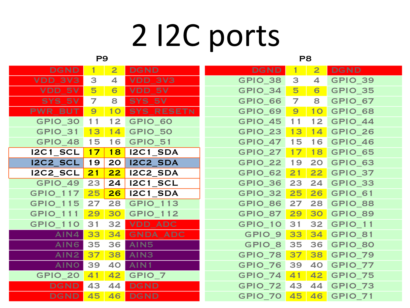
Table of I^2^C outputs
Once the I^2^C device is wired up, you can use a couple handy I^2^C tools to test the device. Because these are Linux command-line tools, you have to use +2+ as the bus number. +i2cdetect+, shown in javascript I2C tools <js_i2cTools>, shows which I^2^C devices are on the bus. The +-r+ flag indicates which bus to use. Our TMP101 is appearing at address 0x498. You can use the +i2cget+ command to read the value. It returns the temperature in hexidecimal and degrees C. In this example, 0x18 = 24{deg}C, which is 75.2{deg}F. (Hmmm, the office is a bit warm today.) Try warming up the TMP101 with your finger and running *i2cget again.
I^2^C tools
bone$ i2cdetect -y -r 2
  0  1  2  3  4  5  6  7  8  9  a  b  c  d  e  f
  00:          -- -- -- -- -- -- -- -- -- -- -- -- --
  10: -- -- -- -- -- -- -- -- -- -- -- -- -- -- -- --
  20: -- -- -- -- -- -- -- -- -- -- -- -- -- -- -- --
  30: -- -- -- -- -- -- -- -- -- -- -- -- -- -- -- --
  40: -- -- -- -- -- -- -- -- -- 49 -- -- -- -- -- --
  50: -- -- -- -- UU UU UU UU -- -- -- -- -- -- -- --
  60: -- -- -- -- -- -- -- -- -- -- -- -- -- -- -- --
  70: -- -- -- -- -- -- -- --

bone$ i2cget -y 2 0x49
  0x18
Reading the temperature via the kernel driver
The cleanest way to read the temperature from at TMP101 sensor is to use the kernel drive.
Assuming the TMP101 is on bus 2 (the last digit is the bus number)
I^2^C TMP101 via Kernel
bone$ cd /sys/class/i2c-adapter/
bone$ ls
i2c-0  i2c-1  i2c-2                   # Three i2c busses (bus 0 is internal)
bone$ cd i2c-2        # Pick bus 2
bone$ ls -ls
0 --w--w---- 1 root gpio 4096 Jul  1 09:24 delete_device
0 lrwxrwxrwx 1 root gpio    0 Jun 30 16:25 device -> ../../4819c000.i2c
0 drwxrwxr-x 3 root gpio    0 Dec 31  1999 i2c-dev
0 -r--r--r-- 1 root gpio 4096 Dec 31  1999 name
0 --w--w---- 1 root gpio 4096 Jul  1 09:24 new_device
0 lrwxrwxrwx 1 root gpio    0 Jun 30 16:25 of_node -> ../../../../../../../../firmware/devicetree/base/ocp/interconnect@48000000/segment@100000/target-module@9c000/i2c@0
0 drwxrwxr-x 2 root gpio    0 Dec 31  1999 power
0 lrwxrwxrwx 1 root gpio    0 Jun 30 16:25 subsystem -> ../../../../../../../../bus/i2c
0 -rw-rw-r-- 1 root gpio 4096 Dec 31  1999 uevent
Assuming the TMP101 is at address 0x48:
bone$ echo tmp101 0x49 > new_device
This tells the kernel you have a TMP101 sensor at address 0x49. Check the log to be sure.
bone$ dmesg -H | tail -3
[ +13.571823] i2c i2c-2: new_device: Instantiated device tmp101 at 0x49
[  +0.043362] lm75 2-0049: supply vs not found, using dummy regulator
[  +0.009976] lm75 2-0049: hwmon0: sensor 'tmp101'
Yes, it’s there, now see what happened.
bone$ ls
2-0049  delete_device  device  i2c-dev  name
new_device  of_node  power  subsystem  uevent
Notice a new directory has appeared. It’s for i2c bus 2, address 0x49. Look into it.
bone$ cd 2-0048/hwmon/hwmon0
bone$ ls -F
device@  name  power/  subsystem@  temp1_input  temp1_max
temp1_max_hyst  uevent  update_interval
bone$ cat temp1_input
24250
There is the temperature in milli-degrees C.
Other i2c devices are supported by the kernel. You can try the Linux Kernel Driver Database, https://cateee.net/lkddb/ to see them.
Once the driver is in place, you can read it via code. i2c temprature python code shows how to read the TMP101 from BoneScript.
Reading an I^2^C device (i2cTemp.py)
include::code/i2cTemp.py[]
.Reading an I^2^C device (i2cTemp.js)
include::code/i2cTemp.js[]
Run the code by using the following command:
bone$ ./i2cTemp.js
data (C) = 25.625
data (C) = 27.312
data (C) = 28.187
data (C) = 28.375
^C
Notice using the kernel interface gets you more digits of accuracy.
Reading i2c device directly
The TMP102 sensor can be read directly with i2c commands rather than using the kernel driver. First you need to install the i2c module.
bone$ pip install smbus
Reading an I^2^C device (i2cTemp.py) .. code-block:: python
include::code/i2ctmp101.py[]
This gets only 8 bits for the temperature. See the TMP101 datasheet for details on how to get up to 12 bits.
Discussion
Reading Temperature via a Dallas 1-Wire Device
Problem
You want to measure a temperature using a Dallas Semiconductor DS18B20 temperature sensor.
Solution
I need to double-check how we provide attribution for recipes, but we’ll need to have something more than “From” followed by a link. For now, we should at least do something like what I’ve changed it to. –BS
–may A bigger question is, when do we need attribution? I pull bits and pieces from everywhere and try to keep good records of sources.
The DS18B20 is an interesting temperature sensor that uses Dallas Semiconductor’s 1-wire interface. The data communication requires only one wire! (However, you still need wires from ground and 3.3 V.) You can wire it to any GPIO port.
To make this recipe, you will need:
Breadboard and jumper wires (see app proto)
4.7 kΩ resistor (see app resistor)
DS18B20 1-wire temperature sensor (see app ic)
Wire up as shown in 1 wire sensor.
Note
This solution, written by Elias Bakken (@AgentBrum), originally appeared on`Hipstercircuits http://bit.ly/1FaRbbK`_.
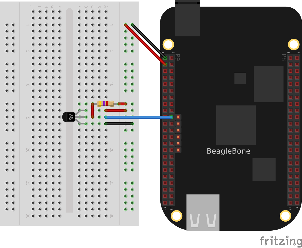
Wiring a Dallas 1-Wire temperature sensor
Edit the file +/boot/uEnt.txt+. Go to about line 19 and edit as shown:
17 ###
18 ###Additional custom capes
19 uboot_overlay_addr4=BB-W1-P9.12-00A0.dtbo
20 #uboot_overlay_addr5=<file5>.dtbo
Be sure to remove the +#+ at the beginning of the line.
Reboot the bone:
bone$ reboot
Now run the following command to discover the serial number on your device:
bone$ ls /sys/bus/w1/devices/
28-00000114ef1b  28-00000128197d  w1_bus_master1
I have two devices wired in parallel on the same P9_12 input. This shows the serial numbers for all the devices.
Finally, add the code in onewire sensor code in to a file named w1.py, edit the path assigned to +w1+ so that the path points to your device, and then run it.
Reading a temperature with a DS18B20 (w1.py)
include::code/w1.py[]
Reading a temperature with a DS18B20 (w1.js)
include::code/w1.js[]
bone$ ./w1.js
temp (C) = 28.625
temp (C) = 29.625
temp (C) = 30.5
temp (C) = 31.0
^C
Discussion
Each temperature sensor has a unique serial number, so you can have several all sharing the same data line.
Playing and Recording Audio
Problem
BeagleBone doesn’t have audio built in, but you want to play and record files.
Solution
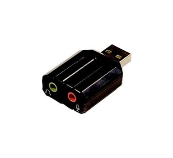
One approach is to buy an audio cape (app capes), but another, possibly cheaper approach is to buy a USB audio adapter, such as the one shown in usb audio dongle. Some adapters that I’ve tested are provided in app musc.
A USB audio dongle
Drivers for the `Advanced Linux Sound Architecture http://bit.ly/1MrAJUR`_ (ALSA) are already installed on the Bone. You can list the recording and playing devices on your Bone by using +aplay+ and +arecord+, as shown in alsa sensors. BeagleBone Black has audio-out on the HDMI interface. It’s listed as card 0 in also sensor. card 1 is my USB audio adapter’s audio out.
Listing the ALSA audio output and input devices on the Bone
bone$ aplay -l
**** List of PLAYBACK Hardware Devices ****
card 0: Black [TI BeagleBone Black], device 0: HDMI nxp-hdmi-hifi-0 []
  Subdevices: 1/1
  Subdevice #0: subdevice #0
card 1: Device [C-Media USB Audio Device], device 0: USB Audio [USB Audio]
  Subdevices: 1/1
  Subdevice #0: subdevice #0

bone$ arecord -l
**** List of CAPTURE Hardware Devices ****
card 1: Device [C-Media USB Audio Device], device 0: USB Audio [USB Audio]
  Subdevices: 1/1
  Subdevice #0: subdevice #0
In the aplay output shown in alsa sensor, you can see the USB adapter’s audio out. By default, the Bone will send audio to the HDMI. You can change that default by creating a file in your home directory called ~/.asoundrc and adding the code in asoundrc to it.
Change the default audio out by putting this in ~/.asoundrc (audio.asoundrc)
include::code/audio.asoundrc
You can easily play _.wav_ files with +aplay+:
bone$ aplay test.wav
You can play other files in other formats by installing +mplayer+:
bone$ sudo apt update
bone$ sudo apt install mplayer
bone$ mplayer test.mp3
Discussion
Adding the simple USB audio adapter opens up a world of audio I/O on the Bone.