Displays and Other Outputs
Introduction
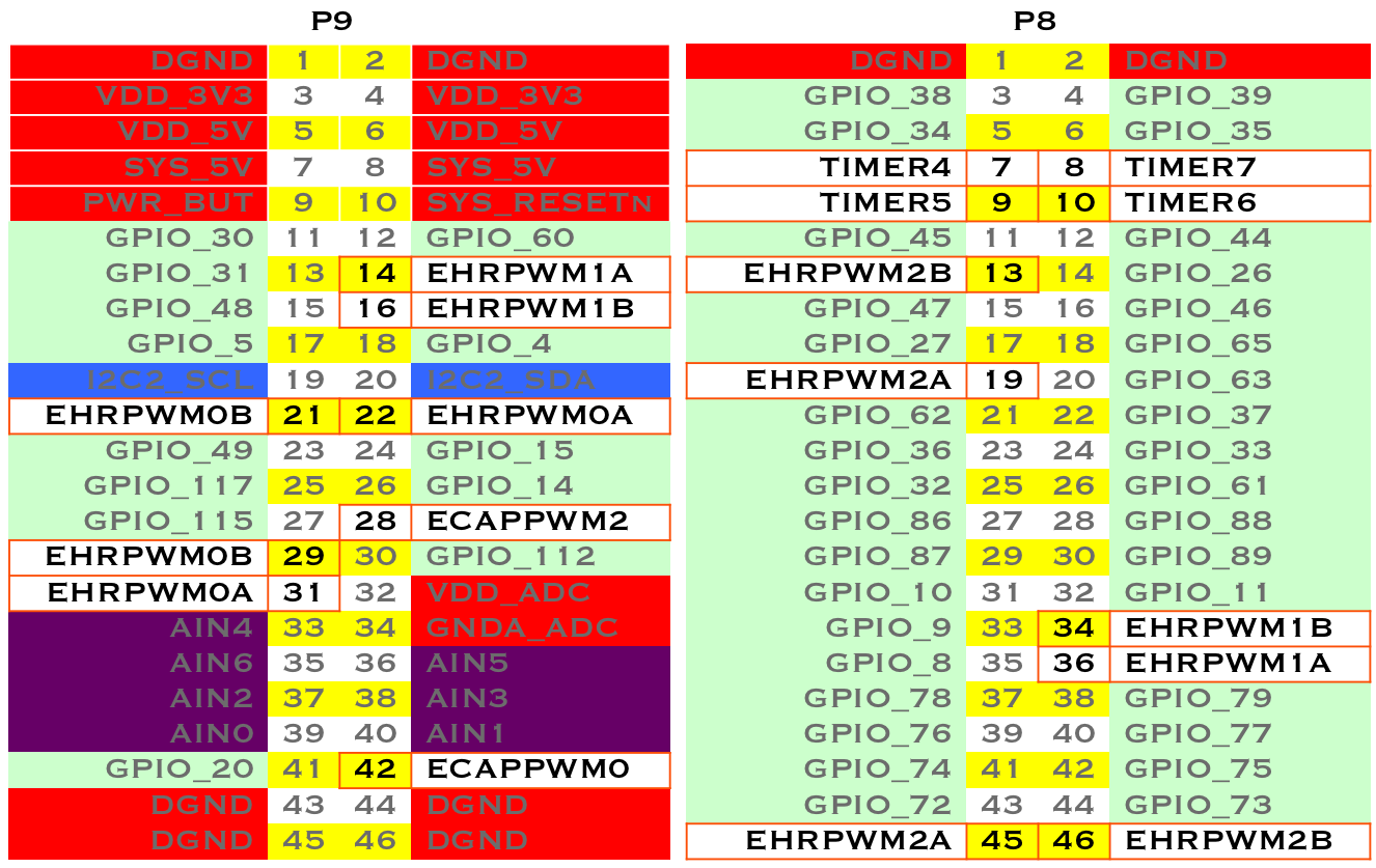
In this chapter, you will learn how to control physical hardware via BeagleBone Black’s general-purpose input/output (GPIO) pins. The Bone has 65 GPIO pins that are brought out on two 46-pin headers, called +P8+ and +P9+, as shown in :ref:`<js_P8P9_fig>>.
Note
All the examples in the book assume you have cloned the Cookbook repository on www.github.com. Go here <basics_repo> for instructions.
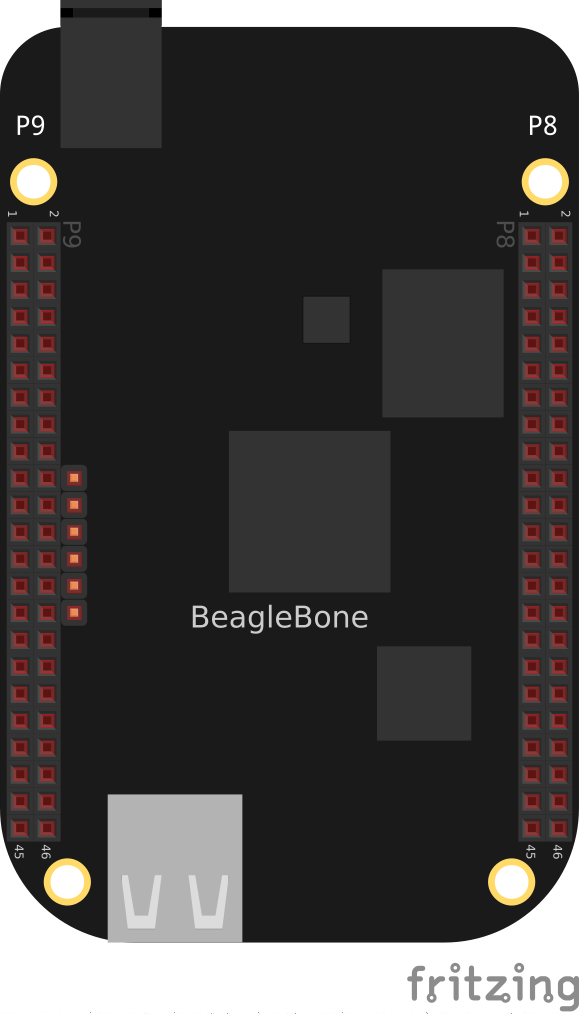
The P8 and P9 GPIO headers
The purpose of this chapter is to give simple examples that show how to use various methods of output. Most solutions require a breadboard and some jumper wires.
All these examples assume that you know how to edit a file (basic vsc) and run it, either within Visual Studio Code (VSC) integrated development environment (IDE) or from the command line (:ref:`<tips_shell>>).
Toggling an Onboard LED
Problem
You want to know how to flash the four LEDs that are next to the Ethernet port on the Bone.
Solution
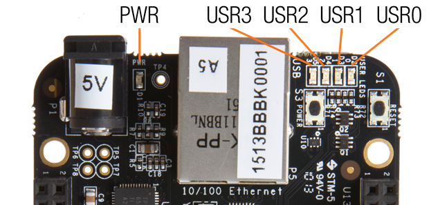
Locate the four onboard LEDs shown in :ref:`<js_internLED_fig>>. They are labeled +USR0+ through +USR3+, but we’ll refer to them as the +USER+ LEDs.
The four +USER+ LEDs
Place the code shown in <js_internLED_code> in a file called _internLED.js_. You can do this using VSC to edit files (as shown in basic vsc) or with a more traditional editor (as shown in :ref:`<tips_editing_files>>).
Using an internal LED (internLED.py)
include::code/internLED.py
Using an internal LED (internLED.js)
include::code/internLED.js
In the +bash+ command window, enter the following commands:
bone$ cd ~/BoneCookbook/docs/03displays/code
bone$ ./internLED.js
The +USER0+ LED should now be flashing.
Discussion
Toggling an External LED
Problem
You want to connect your own external LED to the Bone.
Solution
Connect an LED to one of the GPIO pins using a series resistor to limit the current. To make this recipe, you will need:
Breadboard and jumper wires (see app proto)
220 Ω to 470 Ω resistor (see app resistor)
LED (see app opto)
Warning
The value of the current limiting resistor depends on the LED you are using. The Bone can drive only 4 to 6 mA, so you might need a larger resistor to keep from pulling too much current. A 330 Ω or 470 Ω resistor might be better.
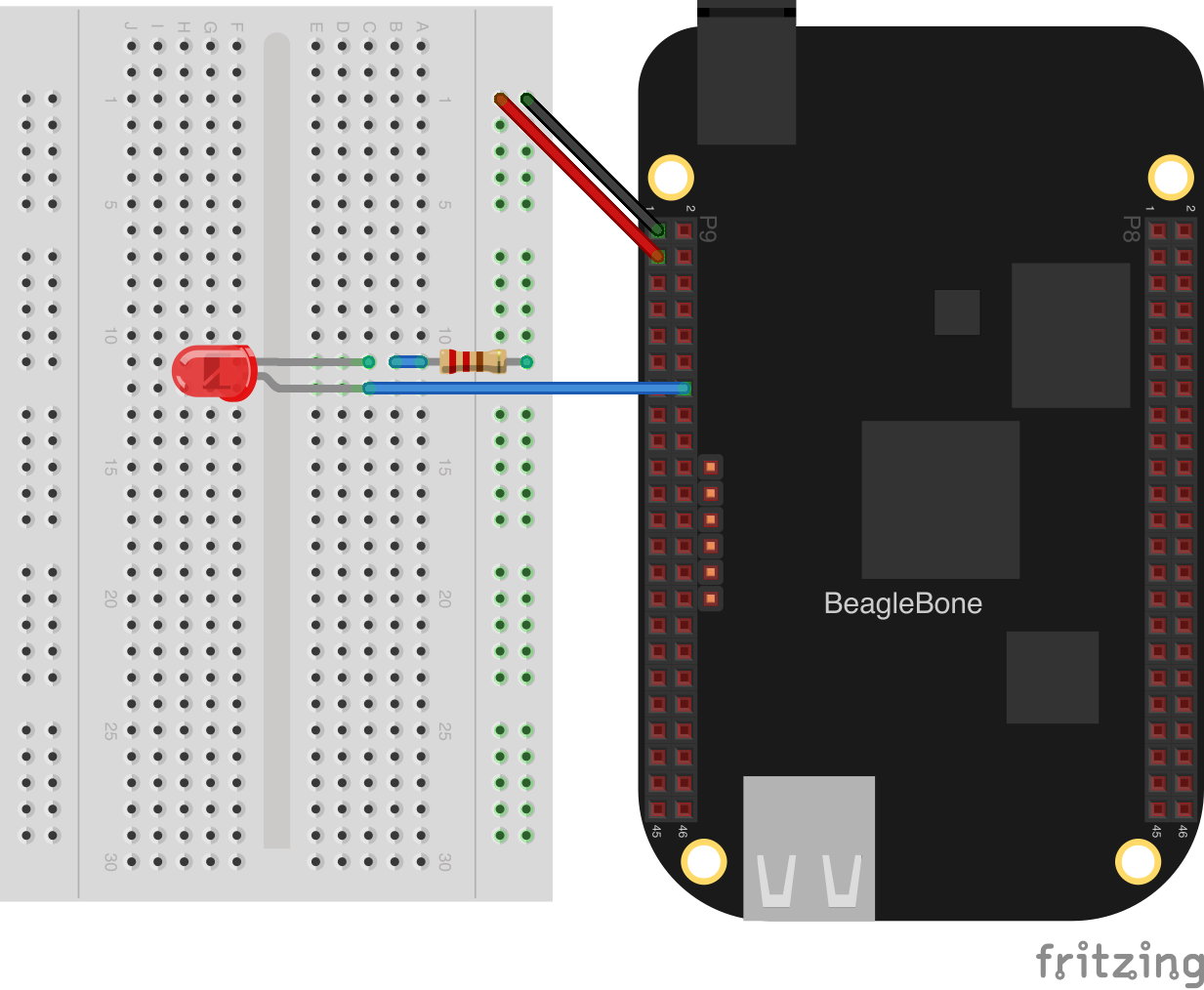
<displays_externLED_fig> shows how you can wire the LED to pin 14 of the +P9+ header (+P9_14+). Every circuit in this book (:ref:`<basics_wire_breadboard>>) assumes you have already wired the rightmost bus to ground (+P9_1+) and the next bus to the left to the 3.3 V (+P9_3+) pins on the header. Be sure to get the polarity right on the LED. The _short_ lead always goes to ground.
Diagram for using an external LED
After you’ve wired it, start VSC (see basic vsc) and find the code shown in :ref:`<py_externLED_code>>.
Code for using an external LED (externLED.py)
include::code/externLED.py
Code for using an external LED (externLED.js)
include::code/externLED.js
Save your file and run the code as before (:ref:`<displays_onboardLED>>).
Discussion
Toggling a High-Voltage External Device
Problem
You want to control a device that runs at 120 V.
Solution
Working with 120 V can be tricky–even dangerous–if you aren’t careful. Here’s a safe way to do it.
To make this recipe, you will need:
PowerSwitch Tail II (see :ref:`<app_misc>>)
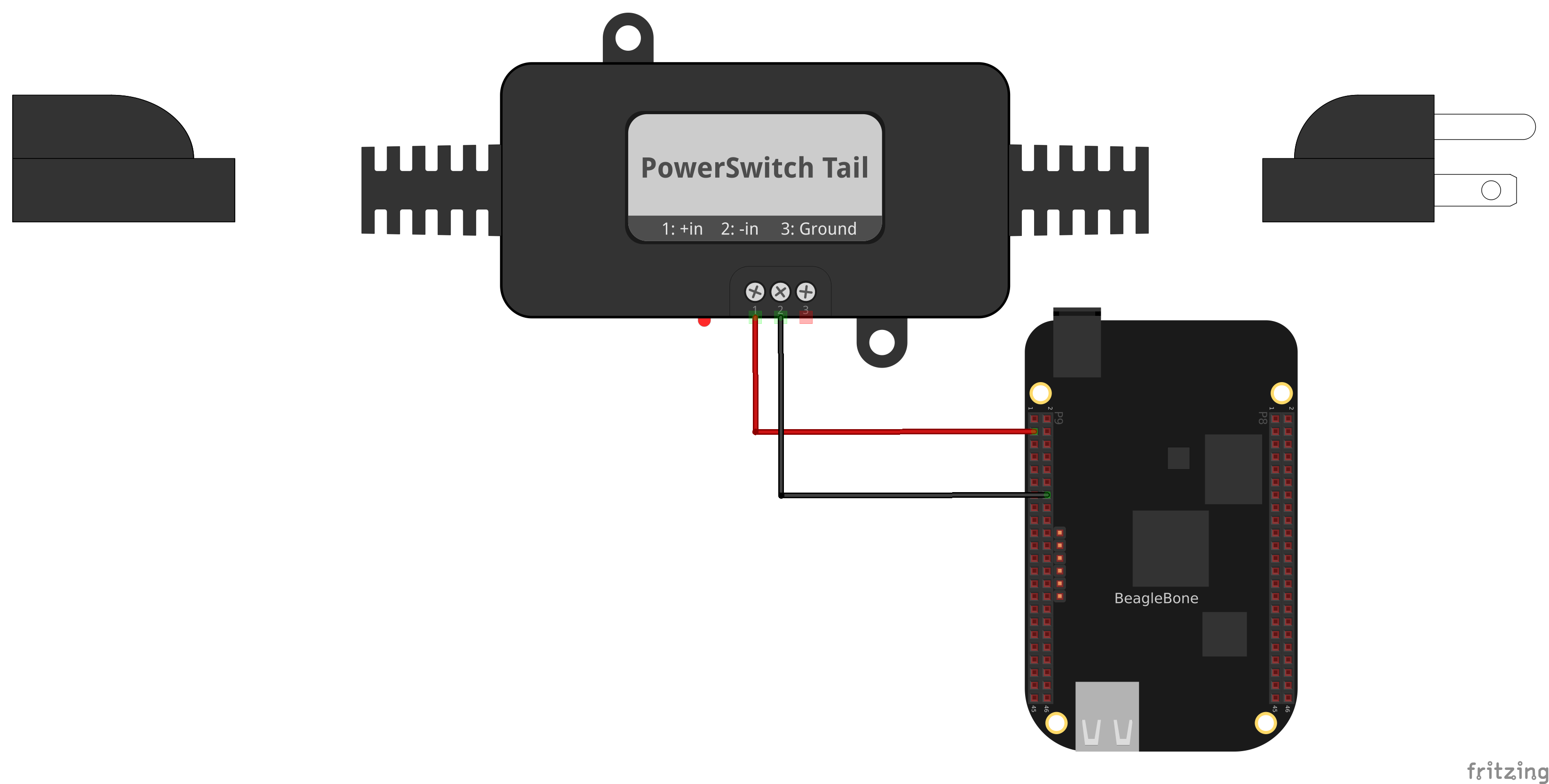
<displays_powerSwitch_fig> shows how you can wire the PowerSwitch Tail II to pin +P9_14+.
Diagram for wiring PowerSwitch Tail II
After you’ve wired it, because this uses the same output pin as :ref:`<displays_externalLED>>, you can run the same code (:ref:`<py_externLED_code>>).
Discussion
Fading an External LED
Problem
You want to change the brightness of an LED from the Bone.
Solution
Use the Bone’s pulse width modulation (PWM) hardware to fade an LED. We’ll use the same circuit as before (:ref:`<displays_externLED_fig>>). Find the code in :ref:`<py_fadeLED_code>>Next configure the pins. We are using P9_14 so run:
Then run it as before.
Code for using an external LED (fadeLED.py)
include::code/fadeLED.py
Code for using an external LED (fadeLED.js)
include::code/fadeLED.js
Discussion
The Bone has several outputs that can be use as pwm’s as shown in :ref:`<cape-headers-pwm_fig>>. There are three +EHRPWM+’s which each has a pair of pwm channels. Each pair must have the same period.
Table of PWM outputs
The pwm’s are accessed through +/dev/bone/pwm+
bone$ cd /dev/bone/pwm
bone$ ls
0  1  2
Here we see six pwmchips that can be used, each has two channels. Explore one.
bone$ cd 1
bone$ ls
a  b
bone$ cd a
bone$ ls
capture  duty_cycle  enable  period  polarity  power  uevent

Here is where you can set the period and duty_cycle (in ns) and enable the pwm.
Attach in LED to P9_14 and if you set the period long enough you can see the LED flash.
bone$ echo 1000000000 > period
bone$ echo  500000000 > duty_cycle
bone$ echo 1 > enable
Your LED should now be flashing.
<display_pwm_mapping> are the mapping I’ve figured out so far. I don’t know how to get to the timers.
Headers to pwm channel mapping.
Pin |
pwm |
channel |
P9_31 |
0 |
a |
P9_29 |
0 |
b |
P9_14 |
1 |
a |
P9_16 |
1 |
b |
P8_19 |
2 |
a |
P8_13 |
2 |
b |
Writing to an LED Matrix
Problem
You have an I^2^C-based LED matrix to interface.
Solution
There are a number of nice LED matrices that allow you to control several LEDs via one interface. This solution uses an Adafruit Bicolor 8x8 LED Square Pixel Matrix w/I^2^C Backpack.
To make this recipe, you will need:
Breadboard and jumper wires (see app proto)
Two 4.7 kΩ resistors (see app resistor)
I^2^C LED matrix (see app opto)
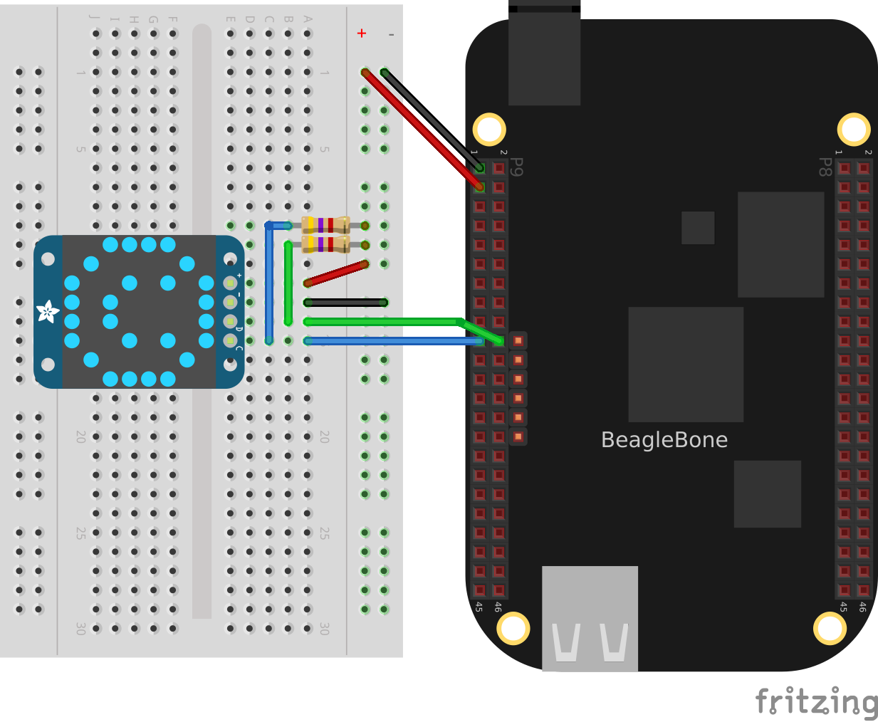
The LED matrix is a 5 V device, but you can drive it from 3.3 V. Wire, as shown in :ref:`<displays_i2cMatrix_fig>>.
Wiring an I^2^C LED matrix
<sensors_i2c_temp> shows how to use +i2cdetect+ to discover the address of an I^2^C device.
Run the +i2cdetect -y -r 2+ command to discover the address of the display on I^2^C bus 2, as shown in :ref:`<displays_i2cdetect>>.
Using I^2^C command-line tools to discover the address of the display
bone$ i2cdetect -y -r 2
     0  1  2  3  4  5  6  7  8  9  a  b  c  d  e  f
00:          -- -- -- -- -- -- -- -- -- -- -- -- --
10: -- -- -- -- -- -- -- -- -- -- -- -- -- -- -- --
20: -- -- -- -- -- -- -- -- -- -- -- -- -- -- -- --
30: -- -- -- -- -- -- -- -- -- -- -- -- -- -- -- --
40: -- -- -- -- -- -- -- -- -- 49 -- -- -- -- -- --
50: -- -- -- -- UU UU UU UU -- -- -- -- -- -- -- --
60: -- -- -- -- -- -- -- -- -- -- -- -- -- -- -- --
70: 70 -- -- -- -- -- -- --
Here, you can see a device at +0x49+ and +0x70+. I know I have a temperature sensor at +0x49+, so the LED matrix must be at +0.70+.
Find the code in <displays_matrix_i2c> and run it by using the following command:
bone$ pip install smbus  # (Do this only once.)
bone$ ./matrixLEDi2c.py
LED matrix display (matrixLEDi2c.py)
include::code/matrixLEDi2c.py
<1> This line states which bus to use. The last digit gives the BoneScript bus number.
<2> This specifies the address of the LED matrix, +0x70+ in our case.
<3> This indicates which LEDs to turn on. The first byte is for the first column of _green_ LEDs. In this case, all are turned off. The next byte is for the first column of _red_ LEDs. The hex +0x3c+ number is +0b00111100+ in binary. This means the first two red LEDs are off, the next four are on, and the last two are off. The next byte (+0x00+) says the second column of _green_ LEDs are all off, the fourth byte (+0x42+ = +0b01000010+) says just two +red+ LEDs are on, and so on. Declarations define four different patterns to display on the LED matrix, the last being all turned off.
<4> Send three commands to the matrix to get it ready to display.
<5> Now, we are ready to display the various patterns. After each pattern is displayed, we sleep a certain amount of time so that the pattern can be seen.
<6> Finally, send commands to the LED matrix to set the brightness. This makes the disply fade out and back in again.
Discussion
Driving a 5 V Device
Problem
You have a 5 V device to drive, and the Bone has 3.3 V outputs.
Solution
If you are lucky, you might be able to drive a 5 V device from the Bone’s 3.3 V output. Try it and see if it works. If not, you need a level translator.
What you will need for this recipe:
A PCA9306 level translator (see app ic)
A 5 V power supply (if the Bone’s 5 V power supply isn’t enough)
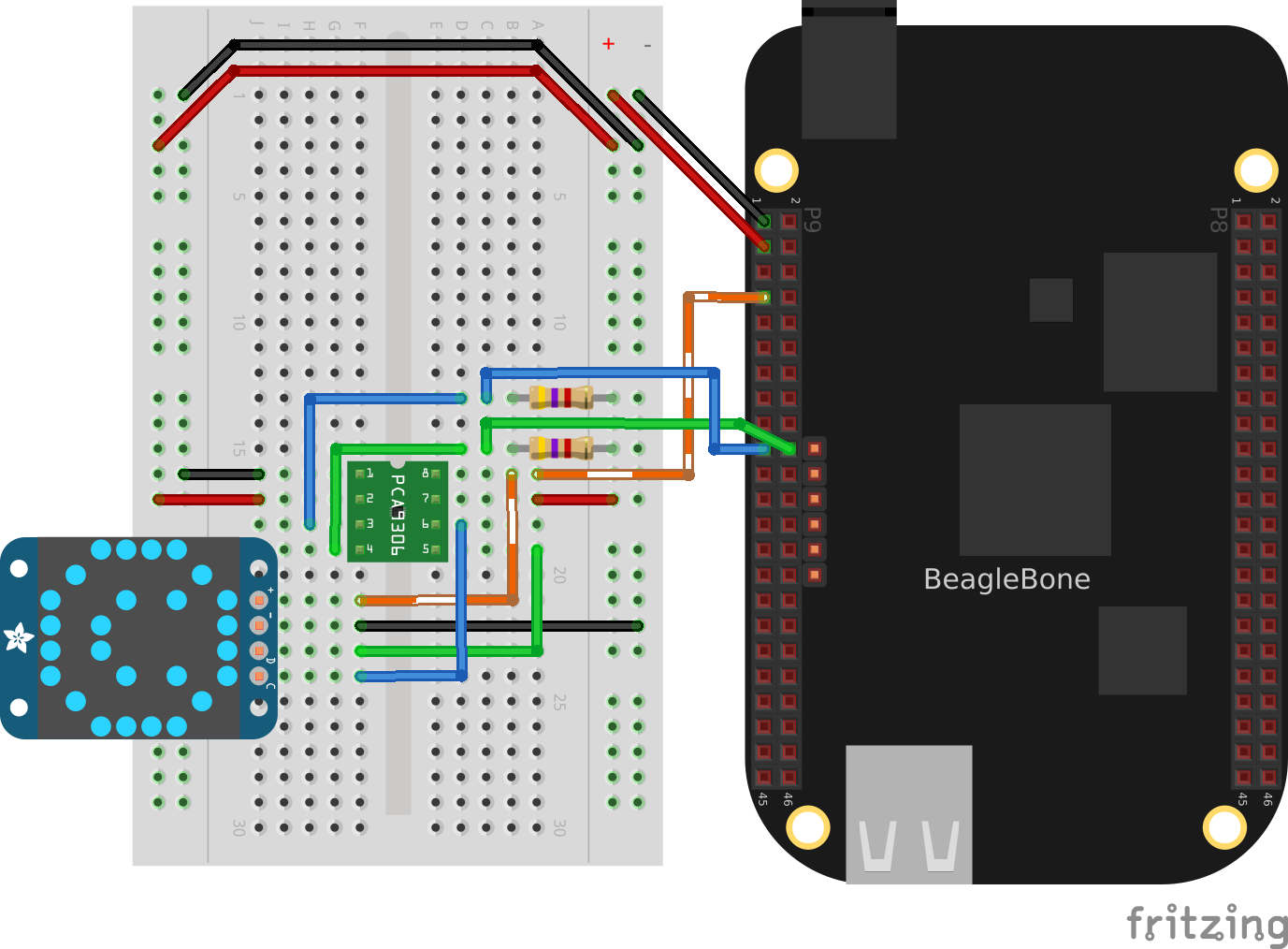
The PCA9306 translates signals at 3.3 V to 5 V in both directions. It’s meant to work with I^2^C devices that have a pull-up resistor, but it can work with anything needing translation.
<displays_i2cMatrixLevelTrans_fig> shows how to wire a PCA9306 to an LED matrix. The left is the 3.3 V side and the right is the 5 V side. Notice that we are using the Bone’s built-in 5 V power supply.
Wiring a PCA9306 level translator to an LED matrix
Note
If your device needs more current than the Bone’s 5 V power supply provides, you can wire in an external power supply.
Discussion
Writing to a NeoPixel LED String Using the PRUs
Problem
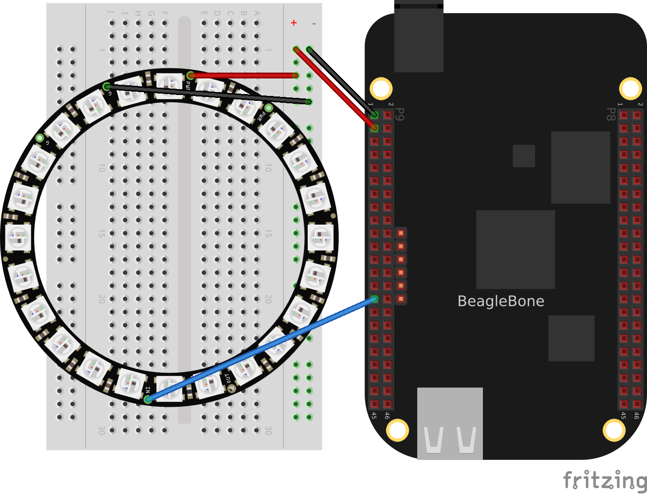
You have an :ref:`Adafruit NeoPixel LED string <http://www.adafruit.com/products/1138>`_ or Adafruit NeoPixel LED matrix and want to light it up.
Solution
The PRU Cookbook has a nice discussion (https://markayoder.github.io/PRUCookbook/05blocks/blocks.html#blocks_ws2812[WS2812 (NeoPixel) driver]) on driving NeoPixels.
Wiring an Adafruit NeoPixel LED matrix to +P9_29+
Writing to a NeoPixel LED String Using LEDscape
Making Your Bone Speak
Problem
Your Bone wants to talk.
Solution
Just install the _flite_ text-to-speech program:
bone$ sudo apt install flite
Then add the code from <speak_code> in a file called _speak.js_ and run.
A program that talks (speak.js)
include::code/speak.js
See <sensors_audio> to see how to use a USB audio dongle and set your default audio out.